Pulse Width Modulation, also known as PWM, is a powerful technique for controlling analog circuits with a processor’s digital outputs. PWM, or a PWM pulse width modulator, is a method of producing variable voltage using a series of digital pulses to simulate a varying analog signal. By tactfully switching the power supplied to a device on and off at a rapid pace—far quicker than the device can physically respond—the power flow deliciously averages out, emitting the illusion of a consistent controlled voltage level. This versatile approach has become a foundational cornerstone for a myriad of applications, from the subtle dimming of LED lights to the robust control of the motors’ speed.
Introduction to Pulse Width Modulation
Modulation, at its core, is about encoding information or manipulating a signal to control its performance, and PWM proves outstanding in the digital world for its extraordinary efficiency and precision. At its purest, simple form, a PWM pulse width modulator skillfully modifies the width of pulses in a series to influence how much energy is delivered to a device. Its significance cannot be understated—in every crevice from hand-held gadgets to towering industrial machinery, PWM shines as a straightforward yet brilliant method for ensuring devices operate exactly as we desire.
The Fundamentals of PWM
The concept of pulse width modulation may initially appear complex, but fundamentally, it’s an elegant solution to a substantial problem. Imagine needing to control the glow of a lamp or the breeze from a fan; adjusting the voltage sent to these devices can be inefficient and potentially harmful. Enter voltage controlled PWM, which optimizes the duty cycle—the ratio of the ‘on’ time against the ‘off’ time within an established time frame. Consequently, it’s a master at overseeing the average power flowing to any load, bypassing inefficient energy loss through resistance.
PWM signals are often crafted in a pwm generator circuit, boasting two paramount characteristics: frequency and duty cycle. The frequency determines how swiftly the PWM executes a full cycle—encompassing both the ‘on’ and ‘off’ phase, dictating the rate at which the device is being energized and de-energized. In stark contrast, the duty cycle illustrates the time segment of one cycle in which the signal retains its high state. Manipulating these twin pillars allows PWM to command the exact measure of power routed to various electrical fixtures.
Applications of Pulse Width Modulation
The reach of PWM extends far and wide with several prime examples including:
- Motor Speed Control: By subtly interchange the duty cycle, one can vary the average power dispatched to a motor. This, in turn, adjusts the speed—a simple tactic to determine how quickly or gradually a motor should churn.
- LED Dimming: The brilliance of an LED can be finessed by modulating the duty cycle, hence controlling the average current passing through; this pwm voltage control ensures brightness variation without the need for a power-leeching variable resistor.
| Application | Controlled Parameter |
|---|---|
| Motor Control | Speed |
| LED Lighting | Brightness |
| Power Supplies | Output Voltage |
| Audio Equipment | Audio Signal and Volume |
In addition to these uses, voltage controlled PWM is essential in power supply regulation, empowering switched-mode power supplies to maintain a consistent voltage output, irrespective of fluctuating load conditions. When venturing into audio signal processing, PWM is critical, fashioning and adjusting audio signals for a myriad of multimedia gadgets, ensuring sound clarity and uniformity.
Advantages of Pulse Width Modulation
Delving into the merits of PWM, we uncover several, yet the following points capture its core benefits:
- Energy Efficiency: Notably energy-efficient, PWM pulse width modulators cleverly switch power, evading the waste of energy conversion into heat—this trait marks PWM as an eco-conscious choice.
- Enhanced Control Precision: The granular tunability of the duty cycle facilitates meticulous command of the power drawn by electrical devices. This nurtures superior functionality and nimble responsiveness.
As we progress further into the realms of electronics and electrical engineering, the importance and benefits of PWM make understanding its mechanics and deployment increasingly crucial. The next segment of this article will delve into PWM signal generation, dissecting the components of a pwm generator circuit and exploring the finer technical nuances of this influential modulation strategy.
PWM Signal Generation and Components
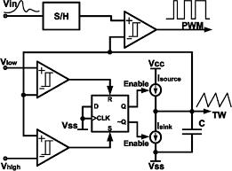
The generation of a PWM signal is a fascinating exercise in precision electronics. At the heart of this process lies the PWM generator circuit, which is responsible for creating the square waveforms that characterize PWM signals. Typically, these circuits will integrate components such as timers, operational amplifiers, or microcontrollers, each playing a pivotal role in the signal’s formation. The signal’s specific shape and timing can also be influenced by additional circuit elements such as resistors and capacitors, which help filter and shape the electrical flow.
Generating signals of desired characteristics involves setting the operational parameters accurately. A PWM controller serves as a cornerstone, a complex yet subtle maestro conducting the temporal dimensions of the pulse. By adjusting elements within the circuit or through software commands in microcontroller-based systems, one can tailor the frequency and duty cycle to match the application’s demands.
- Signal Parameters and Variables: When speaking of parameters and variables, we often refer to the frequency, duty cycle, but also the pulse amplitude and width. These elements are critical as they determine the inherent functionality of the PWM, affecting everything from torque in motors to brightness in LEDs.
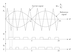
- Comparators and Triangular Wave Generators: These specialized components have a significant function. A Comparator compares a reference voltage with the voltage of a triangular wave, and when the triangular wave’s voltage is higher, it outputs a high signal, contributing to the PWM’s high state.
Understanding PWM in Digital Electronics
When bridging the gap between analog and digital realms, it becomes evident that PWM plays a dual role. Digital signals are inherently on or off, but through the clever use of PWM, they mimic the behavior of analog signals. This makes PWM essential in applications that require a bridge between digital control and analog operation, such as when integrating PWM within microcontrollers.
Analog vs. Digital PWM signals often come up in discussions about signal quality and control fidelity. Digital systems leverage quantization, translating analog inputs into a myriad of discrete values—while digital PWM signals are more resistant to noise and can maintain higher precision over long distances than their analog counterparts.
Integrating PWM with Microcontrollers is typically done through dedicated PWM hardware modules found within the microcontrollers. These modules free up processing resources for other tasks while maintaining precise control over the PWM functions—a feature significant in complex systems where multitasking is paramount.
Conclusion
Pulse Width Modulation is a technological marvel, ingeniously simple yet incredibly versatile. From smoothing out voltage supply to sculpting waveforms for synthesizers, PWM is a linchpin in the vast machinery of modern electronics. It’s the silent puppeteer, dexterously pulling the strings, enabling precise control over the power and performance of countless devices. As we continue to push boundaries in efficiency and precision, PWM’s role can only grow in significance.
Frequently Asked Questions
- What is the primary advantage of using PWM over direct voltage control? PWM’s primary advantage is its energy efficiency; it can control the power supplied to a load without converting excess energy into heat, making it a more environmentally and economically sensible method.
- Can PWM be used for analog signals, or is it limited to digital applications? PWM is primarily a technique used in digital electronics to simulate analog-like behavior, but its output can indeed control analog circuits by employing proper filtering to smooth out the digital pulse train into a quasi-analog signal.
- What adjustments can be made to a PWM signal to control device performance? Adjusting the frequency or duty cycle of a PWM signal can markedly change device performance; for example, a higher duty cycle typically results in more power supplied to the load leading to increased speeds in motors or brighter lights in LEDs.
- Are there any limitations to using PWM? Limitations to using PWM can include potential issues with electromagnetic interference (EMI), requirements for specific filtering components for certain applications, and the need for technical expertise to configure PWM signals correctly.
- How do microcontrollers integrate PWM, and what are the benefits of this integration? Microcontrollers typically integrate PWM through dedicated hardware modules which allow precise control with minimal CPU resource usage. This is advantageous in complex systems where multitasking is needed, and uptime is critical.